More on filters and bandpasses
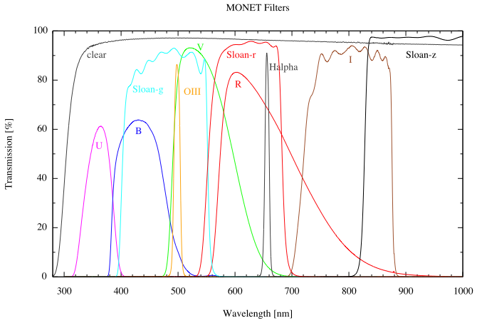
(The above graphic comes from http://monet.uni-goettingen.de/foswiki/MonetObserving/Filters)
This image has real transmission curves for 11 different filters available at a particular camera+telescope. Of these curves, the easiest one to understand is 'clear' -- that one lets everything longward of ~300 nm through to the detector.
Inamongst the other lines there, you can find:
- U - magenta line
- B - blue line
- V - green line
- R - red line
- I - brown line
- and some sloan bands - sloan g, r, and z
- and some narrowband filters - OIII and Halpha
You can see that the central wavelengths are something like:
- U - 0.36 um = 360 nm
- B - 0.44 um = 440 nm
- V - 0.55 um = 550 nm
- R - 0.71 um = 710 nm
- I - 0.79 um = 790 nm
- sloan g - 4810 A = 0.481 um = 480 nm
- sloan r - 6230 A = 0.623 um = 623 nm
- sloan z - 9060 A = 0.906 um = 906 nm
So. What does UVRcIc stand for?
Formally, U means that transmission curve above, centered at 360 nm. The human eye doesn't see much wavelengths shorter than 370 nm or so. So, you can approximately think of "U" as "ultraviolet", though there are lots more ultraviolet wavelengths shortward of this filter that are also ultraviolet.
Formally, B means that transmission curve above, centered at 440 nm. You'd see that as blue for sure.
Formally, V means that transmission curve above, centered at 550 nm. You'd see that as green. Note that it's not the only use of 'visible' light here as certainly you see the B filter as blue and the R filter as red.
Formally, R with no subscripts means that filter above, also known as Johnson R, and the Rc you often see means "Cousins R" which is a slightly different transmission curve. The central wavelength is 710 nm, which is almost too red for you to see with your eyes. According to some simple Googling, assuming the website I landed on has any accordance with reality (it seems reliable), the human eye cuts out circa 730 nm. So this bandpass overlaps with the IR. Note in the transmission curve above, it has a very long tail; it's the least like a square curve of the lot of them. That long tail is what the Cousins R filter is trying to avoid.
Formally, I with no subscripts means that filter above, also known as Johnson I, and the Ic you often see means "Cousins I" which is a slightly different transmission curve. The central wavelength is 790 nm, which is too red for you to see with your eye. There are plenty of IR wavelengths (and standard bandpasses) redward of here, though, so it's not the only IR band.
The Sloan bands are different, and the entire set is 'ugriz' - and I'm not just being sloppy there, they really are not capitalized. This telescope at the link above has g, r, and z in the plot. you can see that they are similar to but different than the standard Johnson filters. Sloan g is sort of B and V together. Sloan r is a much squarer version of Johnson R. Sloan z is far redward of I.
There are some narrowband filters there too -- the Halpha filter is supposed to only really be sensitive to Halpha (not redshifted). Similarly, the OIII filter is only sensitive to that line. (You can see why broadband filters such as UBVRI or ugriz are called 'broadband'.)
These bands are picked as a combination of what materials are available and what kinds of emission you want to study. You can see that Halpha is going to be a prominent contributor to either Sloan r or Johnson R (or Cousins R for that matter). If something is bright in Ha, it will also be bright in those broad bands. Some bands are picked because certain objects (like brown dwarfs) are a much different brightness in those bands.
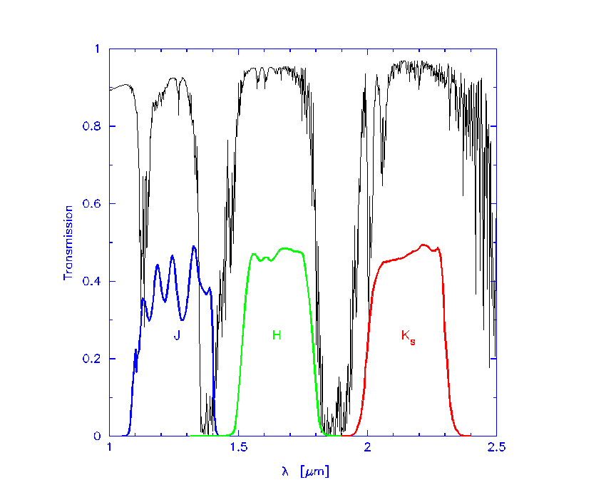
Here are filter transmission curves for the JHKs filters. The black line in that plot is the transmission of the Earth's atmosphere. So, you can probably infer why those bands are positioned where they are. The difference between K and Ks (read as "K-short") refers to the red edge of that K filter - K short truncates the red end a little more than Kjohnson does.
Here are plots of the real transmission curves for IRAC's four channels.
You can find real text file listings of the real filter transmission curves on the web, such as at the link above.
To predict the flux you will get from a particular object, you need to convolve one of those transmission curves with the predicted spectrum from your object, and integrate under the curve.
A COMPLETELY different look at some of the same concepts is here -- this is brightness as a function of wavelength for crayons! admittedly, this is reflection and not transmission, but still.

